Water Technologies & Solutions technical paper
reducing wastewater to dryness: zero liquid discharge case studies at new power plants
Authors: J. Bostjancic and R. Ludlum, Resources Conservation Company (RCC), November 1994
Note: veolia purchased RCC in 2005.
abstract
Increasingly stringent discharge regulations have led several new power plants in Florida to install evaporators and crystallizers to recycle saturated wastewater such as cooling tower blowdown, demineralizer regenerant and reverse osmosis reject. Approximately 95% of these wastewaters are recovered as distillate for reuse in the plant; the remaining slurry is reduced to solids in a crystallizer and landfilled. Three operating zero liquid discharge systems in Florida will be described.
introduction
As wastewater discharge regulations become more stringent, power plants and other industrial sites are looking for ways to reduce makeup water requirements and to recycle and reuse as much wastewater as possible. In some cases, environmental regulations require zero liquid discharge, meaning all wastewater must either be retained on site or reduced to solids for disposal off site. This paper will discuss the zero liquid discharge wastewater recycling systems used by three power plants in Florida. In all cases, an evaporator and crystallizer are the key components of the zero liquid discharge system.
The Evaporator
The heart of each zero discharge system described in this paper is a vertical tube, falling film evaporator driven by a mechanical vapor compressor. While evaporator size and number of units varies, the evaporator design is the same at the three plants described.
The main advantage of using an evaporator for zero discharge systems is the large volume of distilled water recovered for recycling. Depending on wastewater chemistry, the evaporator recovers 95% to 99% of the original wastewater as high purity distilled water (<10 ppm [mg/L] TDS). The distillate may be used as boiler makeup or for other processes requiring high quality water, such as evaporative cooler makeup water for gas turbines and for gas turbine NOx control. Distillate is also used as cooling tower makeup, often to dilute poor quality makeup water.
The Seeded Slurry Process
The evaporator uses a proprietary “seeded slurry” process to concentrate salty wastewaters well beyond their normal saturation point. For example, circulating water is blown down from cooling towers just before it begins to form a scale of calcium sulfate and silica (usually between 2000 and 16,000 ppm [mg/L] TDS). This saturated wastewater can be concentrated another 20 to 80 times in an evaporator with seeded slurry control. Calcium sulfate “seeds” are added to the wastewater during startup. Precipitating calcium sulfate and silica crystallize on the seeds and stay in suspension rather than building up on equipment walls. (The “seeds” are added only during startup; while the evaporator is in operation, new seeds regenerate continuously.) Using the seeded slurry process allows the evaporator to operate for a year or more between cleanings.
Evaporator System Operation
In an evaporator system (Figure 1), wastewater enters a feed tank (not shown) where the pH is adjusted to between 5.5 and 6.0. The acidified wastewater is pumped to a heat exchanger that
Find a contact near you by visiting www.veoliawatertechnologies.com and clicking on “Contact Us.” *Trademark of veolia; may be registered in one or more countries.
©2017 veolia. All rights reserved.
TP1046EN.docx Feb-11
raises its temperature to the boiling point. It then goes to a deaerator, which removes non-condensable gases such as carbon dioxide and oxygen. Hot deaerated feed enters the evaporator sump, where it combines with the recirculating brine slurry. The slurry is pumped to the top of a bundle of 2-inch (5- cm) titanium heat transfer tubes, where it falls by gravity in a thin film down the inside of the tubes. As it falls, a small portion evaporates and the rest falls into the sump to be recirculated.

Figure 1: Evaporator
The vapor travels down the tubes with the slurry, passes through mist eliminators and is compressed in a vapor compressor, which heats it slightly. Compressed vapor flows to the outside of the heat transfer tubes, where its latent heat is given up to the cooler brine slurry falling inside. As the vapor gives up heat, it condenses as distilled water. The distillate is pumped back through the heat exchanger, where it gives up heat to the incoming wastewater.
A small amount of waste brine is continuously released from the evaporator to control the density of the recirculating slurry. Waste brine is reduced to solids in a crystallizer.
Crystallizer
The three power plants discussed in this paper use forced-circulation crystallizers driven by steam (Figure 2) to reduce evaporator waste brine to dry solids. Slurry from the evaporator (waste brine) is pumped to the crystallizer shell and tube heat exchanger (heater). Because the tubes are flooded, the slurry is under pressure and will not boil. This inhibits scaling in the tubes. The recirculating brine inside the tubes is heated with steam sent to the outside of the heat transfer tubes. The steam condenses on the outside of the tubes, giving up its heat to the brine slurry inside. Condensate is collected and may be
recycled in the plant. This water is also quite pure, typically <50 ppm total dissolved solids.
After it is heated, the slurry enters the crystallizer vapor body at an angle, where it swirls in a vortex. A small amount of the brine evaporates. As water is evaporated from the brine, crystals form. Most of the brine is recirculated back to the heater. A small stream from the recirculating brine is sent to a centrifuge or filter to separate the remaining water from the crystals. The purge from the centrifuge or filter is pumped back to the crystallizer. The crystallized salts are landfilled off site.
The vapor in the crystallizer passes through a mist eliminator and then to a condenser. At two of the sites (Case One and Case Two), a thermocompressor is used to recompress a portion the vapor and send it back to the crystallizer heater. This improves steam economy by about 30% and lowers energy costs. The crystallizer in Case Three has no thermocompressor; all vapor is sent directly to a condenser.

Figure 2: Steam-driven crystallizer
case studies
Case One:
920 MW Coal-Fired Baseload Power Plant
This power plant constructed in 1986 will double its generating capacity by mid-1996. The original plant used evaporation and crystallization for zero liquid discharge wastewater treatment. During construction of the enlarged plant, a new evaporation and crystallization system was installed to handle both the existing wastewater and the increased load of cooling tower blowdown expected once the full plant is operating. The original zero discharge system installed in 1986 consisted of two evaporators and two crystallizers. The new system has one large evaporator and two crystallizers (Figure 3) treating 600 gpm (140 m3/h) of cooling tower blowdown. The design feed chemistry is shown in Table 1.
Table 1: Feed to Evaporator, Case One Cooling Tower Blowdown

Cooling tower blowdown is first sent to a holding pond and then to a feed tank. Here chlorine is added to kill the algae formed in the holding pond. Sulfuric acid is also added at this point to adjust the pH to 5.5. A filter then removes any suspended matter 25 microns or larger. The wastewater enters the evaporator system shown in Figure 1. Distillate produced in the evaporator (about 575 gpm or 130 m3/h) is returned to the cooling towers. The evaporator waste brine is sent to one of the crystallizers. Crystallizer operation is shown in Figure 2. Each crystallizer is designed to handle all 25 gpm (5.7 m3/h) of evaporator waste; one
unit is always on standby or being cleaned while the other is working. Slurry from each crystallizer is sent to a centrifuge for final drying. The centrifuge is designed to produce about 26,000 pounds (12,000 kg) of solids per day.
Part of the rationale for the new evaporator/crystallizer configuration is energy savings. The new evaporator was designed with extra-long heat transfer tubes (65 feet [20 m] vs. the normal 50 feet [15 m]). The longer tubes increased capital cost by US$150,000 but is designed to reduce the energy requirement to about 18 kWh per 264 gallon (1 m3) of feed. A typical energy requirement for a 600 gpm (140 m3/h) evaporator would be about
25 kWh per 264 gallon (1 m3) of feed. Figuring
electrical costs at US$0.05 per kWh, long tubes should save the plant about US$425,000 per year in energy costs.

Figure 3: Baseload power plant zero liquid discharge system

Figure 4: Coal-fired cogeneration plant zero liquid discharge system
Case Two:
250 MW Coal-Fired Cogeneration Plant
A zero liquid discharge system as well as many other environmental controls were required at this cogeneration plant in order to obtain permits and gain community acceptance. The plant was completed in January, 1994.
To conserve fresh water, plant makeup water is wastewater from the steam host, (pulp mill) which is cleaned up and used in the cooling towers. Cooling tower blowdown is treated, concentrated and recycled in the evaporator crystallizer system (Figure 4). The power plant also collects various wastewaters in a lined pond: stormwater and runoff from the coal pile, limestone pile and ash pellet area. This wastewater is also treated and reused in the plant.
Wastewater from the pulp mill and cogeneration plant is first sent to a clarifier to remove suspended solids and calcium. A portion of the clarate is returned to the mill and the rest is used as cooling tower makeup. Blowdown from the cooling towers is sent to another clarifier to remove calcium and silica; a sidestream is returned to the cooling towers. The remainder is sent to a nanofilter pretreatment system before treatment in a reverse osmosis (RO) system. RO product water is returned to the cooling towers and the RO reject is sent to the evaporator feed tank. Sulfuric acid is added to adjust the pH to
5.5. Scale inhibitor is also added at this point to prevent calcium sulfate from precipitating until it reaches the evaporator sump. The feed is then divided between the two evaporators (Figure 1). The evaporator feed chemistry is shown in Table 2.
Table 2: Feed to Evaporator, Case Two Cooling Tower Blowdown Concentrated with Reverse Osmosis
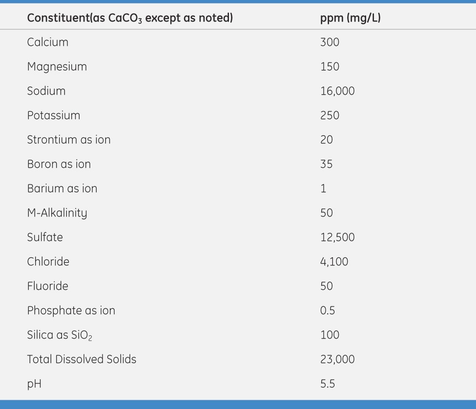
Each evaporator treats 150 gpm (34 m3/h) of wastewater. Normally with a wastewater flow of 300 gpm (68 m3/h), the evaporators would generate about
15 gpm (3.4 m3/h) of waste brine. Because of the chemistry of this feed, however, double salts will form at a relatively low concentration. Therefore waste brine at a rate of 50 gpm
(11 m3/hr) must be blown down from the evaporator to prevent scaling. Waste brine is sent to the crystallizer (Figure 2) followed by a centrifuge to produce about 83,000 pounds (38,000 kg) per day of dry solids for landfill.
Designers of this zero liquid discharge system expected to treat 95 gpm (22 m3/h) of cooling tower blowdown and demineralizer regenerant; two evaporators were ordered, followed by a small crystallizer (Figure 5). In actual operation, only about 45 gpm (10 m3/h) of wastewater is generated at the plant. Therefore, only one evaporator is needed at a time. Each evaporator has a turndown capacity of about 50%, allowing a great deal of system flexibility.
Case Three: 150 MW Combined-Cycle Cogeneration Plant
Cooling tower blowdown and demineralizer regenerant is collected in a waste tank and sent to the evaporator feed tank. The feed chemistry is shown in Table 3. Sulfuric acid is added to adjust the pH to 5.5. Scale inhibitor is also added at this point to
prevent calcium sulfate from precipitating until it reaches the evaporator sump.
From the feed tank, the waste is sent to an in-line filter to remove suspended solids and then to one of the evaporators (Figure 1). Evaporator distillate is used for cooling tower makeup; waste brine is sent to the crystallizer. The crystallizer is essentially the same as pictured in Figure 2, but it does not have a thermocompressor. All crystallizer vapor is sent directly to the condenser. Slurry from the crystallizer is sent to a filter press for final dewatering. The filter press produces about 2,200 pounds (1,000 kg) of solids per day.
 Table 3: Feed to Evaporator, Case Three Wastewater Chemistry

Figure 5: Combined cycle generation plant zero liquid discharge
summary
Water shortages and community pressure have combined to create increasingly stringent wastewater discharge regulations, especially for new power plants in Florida. There are more zero discharge power plants in Florida than any other state in the
U.S. As of late 1994, there are eight operating and a ninth under construction. All are using some combination of evaporation and crystallization to recycle and reuse saturated wastewaters and reduce concentrated waste to solids for disposal.


